If objects are too long to fit in a sheet but have the same shape along their entire length, you can shorten them in Revit with a breakline.
In the next two steps, you will add the default breakline symbol to your views (plans, sections, and elevations). In the third step, you will learn how to create a wavy breakline family.

There are two types common to blueprints: long break lines (zigzag) and short break lines (wavy).
Add Break Line
Details: Load the breakline symbol into your project.
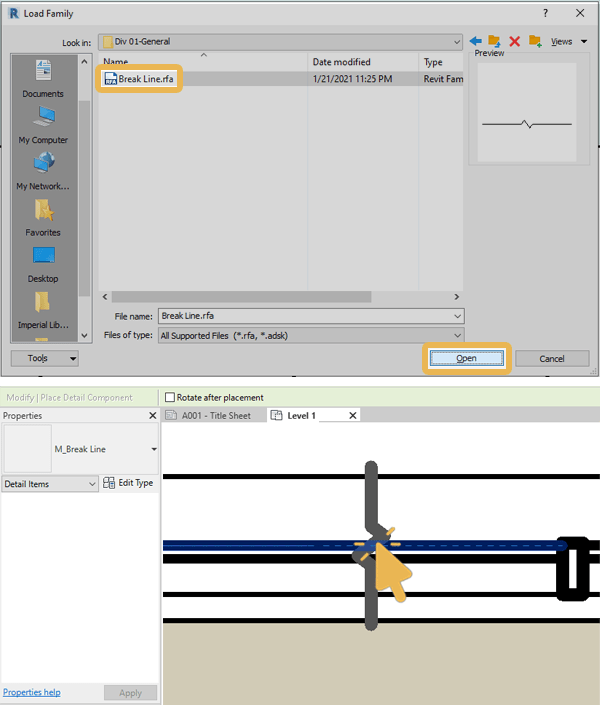
The default family is located at: C:\ProgramData\Autodesk\RVT 20XX\Libraries\English\US\Detail Items\Div 01-General\M_Break Line.rfa.
Steps
- Go to the Annotate tab > Detail panel > drop-down Component menu.
- Click Detail Component.
- In the Modify | Place Detail Component tab, click Load Family.
- Browse to the RFA file, select it and click Open to insert it in view.

✨ Tip: Press Space on the keyboard to rotate the line before inserting it. Read more about Keyboard Shortcuts in Revit.
Edit Family Parameters
Once the family is in place, click on the annotation to use parametric handles for resizing or use the Properties palette to change values of dimensions.


Create Family (optional)
Details: Create an alternative parametric short break line family.
Steps
- Go to File tab > drop-down New menu > click Family.
- Browse to: C:\ProgramData\Autodesk\RVT 20XX\Family Templates\English.
- Select Metric Detail Item.rft > click Open.

- Datum panel > click Reference Plane. Draw four vertical parallel reference planes.
- Dimensions panel > click Aligned. Click on all vertical lines in view, respectively.
- Click EQ to equalize the distance between them.
- Add one overall horizontal dimension, then select it.
- Go to the Label Dimension panel > click on the small Create Parameter icon.
- Name it “Jag_Width” > select Instance under Parameter Data > click OK.
- Datum panel > click Reference Plane > Draw two horizontal planes.
- Add dimensions between all existing 3 horizontal lines > click EQ.
- Add one overall vertical dimension then select it.
- Associate it with a new instance parameter named “Jag_Depth“.
- Add 4 reference planes as a square around the Jag.
- Add two dimensions (vertical and horizontal) for the new external square.
- Assign instance parameters named “depth” for vertical and “width” for horizontal.
- Go to Create tab > Detail panel > click Masking Region.
- Within Draw panel > select Partial Ellipse tool.
- Sketch curves of the symbol.
- Modify panel > Align (Shortcut: AL).
- Select the top reference line > Select the intersecting top point of the arc.
- Lock the alignment > Repeat the process for the second arc with its own reference line.

- Go to Draw panel, select Pick Lines tool.
- Within Options bar, tick Lock > Pick boundary reference lines of the mask region.
- Modify panel > Trim/Extend to corner (Shortcut: TR) picked lines > enclose profile.
- Add one final dimension connecting horizontal ends of the mask profile.
- Select dimension > create a new instance parameter and name it “mask_depth“.
- Select the upper 3 boundary lines > go to the Subcategory panel.
- Drop-down menu > select Invisible Lines.


- Click Finish Edit Mode.
- Go to the Family Editor panel > Load into Project.

The break line symbol can be used to split multiple objects in a view. Learn more about splitting a view into multiple sheets
Mohamed Fakhry has helped thousands of architects and designers find their next project with step-by-step guidance on his blog, mashyo.com. About Mohamed
His journey began during his university years when he recognized the need for information-rich 3D models to accelerate learning and improve production processes. Now, Mohamed shares his expertise through Revit tutorials that are accessible to all.
