
A spot elevation in Revit reports the height of a selected point in your model. You can use it on ramps, roads, toposolids, stair landings, floors, roofs, and many other model edges or surfaces where the height needs to be documented clearly.
As a student, this was one of the tools that made Revit feel much smarter than AutoCAD. I was trying to annotate a roof in a site plan. As I moved the cursor across different surfaces, the elevation value updated before I clicked. That small preview explained the model better than a static 2D note ever could.
Quick Answer
To add a spot elevation in Revit, go to Annotate > Dimension > Spot Elevation, choose a type from the Type Selector, set the leader and elevation display options, then click a model edge or surface. In Revit 2026, the placement options are on the contextual ribbon instead of the old Options Bar workflow.
- Use Actual Elevation for the exact point you click.
- Use Top Elevation, Bottom Elevation, or Top & Bottom Elevations for elements with thickness in plan views.
- Use Relative as the Elevation Base when the value should report from a selected level instead of the project or survey datum.
What Is a Spot Elevation Symbol?
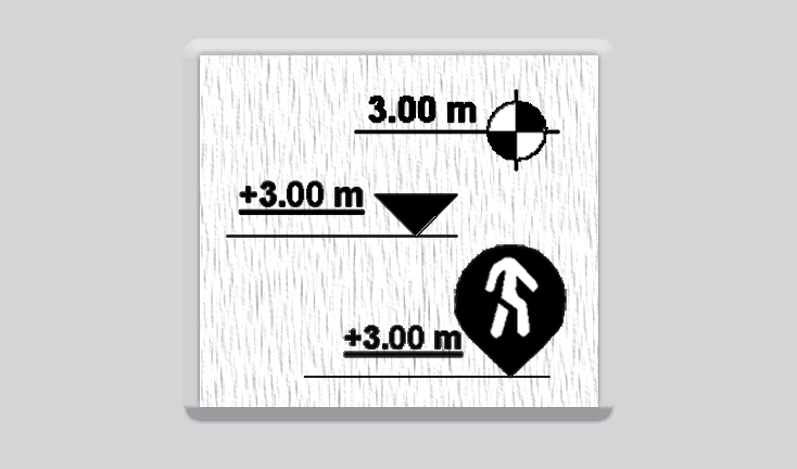
A spot elevation symbol is the annotation marker that displays a point height in a Revit view. It usually includes a symbol, a leader, and one or more elevation values. The value is not manually typed text; it is read from the referenced model geometry and updates when the referenced height changes.
Spot elevations are view-specific annotations. You can place them in plans, elevations, sections, and 3D views. They are especially useful for site plans, roof plans, ramps, slabs, stairs, landings, and coordination views where small level changes matter.

Where Spot Elevations Work Best
Use spot elevations when the drawing needs to communicate a real model height at a specific point. They are more reliable than typing a manual note because the annotation remains connected to the element you selected.
| Use case | Best spot elevation setting | Why it helps |
|---|---|---|
| Site plan or terrain | Actual Elevation | Reports the height at the exact point on the toposolid or linked topography. |
| Roof plan | Actual or Top Elevation | Shows roof heights and slope changes without manual labels. |
| Floor slab plan | Top Elevation | Clarifies finished floor or slab top levels in plan. |
| Foundation or structural plan | Bottom Elevation or Top & Bottom | Helps coordinate structural element depths. |
| Ramps and stairs | Actual Elevation | Documents changing heights along sloped circulation elements. |
How to Add Spot Elevations in Revit
Follow these steps to place a spot elevation annotation:
- Open the view where you want to place the annotation.
- Go to Annotate tab > Dimension panel > click Spot Elevation.
- In the Type Selector, choose the spot elevation type you want to use.
- On the contextual ribbon, choose whether to use a Leader and Shoulder.
- If you are using a relative spot elevation, choose the Relative Base.
- In a plan view, choose Actual Elevation, Top Elevation, Bottom Elevation, or Top & Bottom Elevations.
- Move the cursor over the element. Revit previews the elevation value before placement.
- Click the edge, point, or surface you want to report.
- If you are placing a leader, move the cursor away from the element and click to place the annotation. If you enabled a shoulder, click once for the shoulder and once again for the final text position.
- Press Esc twice to finish.

In older tutorials, you may see the Leader, Shoulder, Relative Base, and Display Elevations controls described as Options Bar settings. In Revit 2026, Autodesk moved several dimension placement controls to the contextual ribbon and Properties Palette. The tool still works the same way, but the controls are no longer in exactly the same place.

Actual, Top, Bottom, and Top & Bottom Elevations
The Display Elevations setting controls what value the annotation reports. This setting is available when you place a spot elevation in a plan view.
- Actual Elevation: reports the elevation of the exact selected point.
- Top Elevation: reports the top of an element with thickness.
- Bottom Elevation: reports the bottom of an element with thickness.
- Top & Bottom Elevations: displays both values in one annotation.
For most architectural floor and site views, Actual Elevation is the safest starting point. Switch to top or bottom values when you are coordinating slab thicknesses, foundations, roof assemblies, or structural levels.
How to Change the Relative Base
A spot elevation can report from three kinds of references: Project Base Point, Survey Point, or a Relative level. This matters because the same physical point can show different numbers depending on which datum the annotation is using.
- Select the spot elevation.
- In the Properties palette, click Edit Type.
- Under Constraints, set Elevation Base to Relative, Project Base Point, or Survey Point.
- If you choose Relative, select the level for Relative Base when placing or editing the annotation.
- Click OK.
Use Relative when the drawing should read levels from a building story, such as Level 01 or Finished Floor Level. Use Survey Point when the drawing needs real-world site elevations. Use Project Base Point when your office standard uses the project datum for coordination.
How to Edit Spot Elevation Text, Units, and Symbol
Most spot elevation appearance settings are controlled by the type. Duplicate the type before editing so you do not accidentally change every spot elevation that uses the same annotation style.
- Select an existing spot elevation.
- In the Properties palette, click Edit Type.
- Click Duplicate and give the type a clear name, such as Spot Elevation – Site Relative.
- Choose the symbol family used by the type.
- Adjust text properties such as text size, font, offset, and indicator labels.
- For units, click the Units Format field.
- Uncheck Use project settings if this spot elevation type needs its own unit format.
- Set units, rounding, unit symbol, and suppression settings.
- Click OK.
If the value is technically correct but looks wrong on the sheet, check the unit format first. A spot elevation rounded to too few decimal places can hide small slopes and slab changes. A unit suffix can also make the annotation look crowded if the symbol is small.
Learn more about changing units in Revit.


How to Load a Different Spot Elevation Symbol
If the symbol you want is not available in the type selector, load it into the project first.
- Go to Insert tab > Load from Library panel > click Load Family.
- Browse to the Revit annotation library for your installed version.
- Open the spot elevation symbol family you want to use.
- Select a spot elevation in the project and click Edit Type.
- Choose the loaded symbol family in the type properties.
The default library path is commonly similar to C:\ProgramData\Autodesk\RVT 20XX\Libraries\English\US\Annotations. Replace 20XX with your installed Revit version.
How to Edit a Spot Elevation Family
Use this workflow when you want to change the graphic shape of the spot elevation symbol itself. For example, you may want a filled target, a square pointer, a custom office symbol, or a simpler marker for small-scale drawings.
- Go to File > Open > Family.
- Browse to
C:\ProgramData\Autodesk\RVT 20XX\Libraries\English\US\Annotations. - Open a family such as M_Spot Elevation – Exterior Filled.rfa.
- Select the filled region or linework that creates the symbol.
- Click Edit Sketch if you are editing a filled region.
- Use the Draw tools to adjust the profile.
- Assign the correct line subcategory, such as visible annotation lines or invisible reference lines.
- Click Finish Edit Mode.
- Save the family with a new office-standard name.
- Click Load into Project.


If the symbol displays in the opposite direction after loading it into the project, reopen the family and mirror or rotate the sketch. Spot elevation symbols can behave differently depending on leader direction, so always test the family in all common placements: left, right, above, and below the point.

Learn about other Revit annotation symbols.
Best Settings for Clean Spot Elevation Graphics
- Duplicate types by purpose: create separate types for site elevations, floor elevations, roof elevations, and structural levels.
- Keep symbols readable: use a simpler symbol for small view scales and a more detailed symbol for larger details.
- Control rounding: use enough precision for the drawing scale and coordination purpose.
- Use consistent prefixes: common examples include T.O.S., B.O.S., FFL, T.O.W., and SSL.
- Avoid manual text over the annotation: if you need a prefix or suffix, add it through the spot elevation type or instance parameters.
- Test before making a template standard: place the symbol with and without a leader, with a shoulder, and in multiple directions.
Why Spot Elevations Show the Wrong Value
If a spot elevation value looks wrong, the problem is usually not the annotation symbol. Check the reference, base, view, and units before rebuilding the family.
| Problem | Likely cause | Fix |
|---|---|---|
| Value is correct in one view but wrong in another | Different Elevation Base or Relative Base | Edit the type and confirm Project Base Point, Survey Point, or Relative level. |
| Spot elevation disappears | The referenced element was deleted or hidden | Restore element visibility or place a new spot elevation on a valid reference. |
| Annotation is too small or too large | View scale affects annotation display | Change the view scale or use a better spot elevation type for that scale. |
| Top and bottom options are unavailable | The view or selected element does not support that display mode | Use a plan view and select an element with thickness. |
| Units look inconsistent | The type uses project units or custom unit formatting | Edit the Units Format parameter and adjust rounding, suffix, and unit symbol. |
Also check whether you are clicking the correct surface. On roofs, ramps, stairs, and toposolids, moving the cursor slightly can change the reported point. Zoom in before placement if the point must be exact.
Spot Elevation Not Working or Not Visible
If spot elevations are not working in one or more views, try these checks in order:
- Zoom in and out to confirm the annotation is not too small for the current view scale.
- Check Visibility/Graphics and confirm annotation categories are visible.
- Confirm the referenced model element is visible in the view.
- Try placing the spot elevation on a clear edge instead of a crowded overlapping surface.
- Switch the Display Elevations setting to Actual Elevation and test again.
- Check whether a view template is hiding dimensions, annotation categories, or the referenced model category.
Spot elevations are tied to their references. If the referenced element is deleted, hidden, or no longer valid in that view, the spot elevation can be removed or fail to display correctly.
FAQ
What is a spot elevation in Revit?
A spot elevation is a Revit annotation that displays the elevation of a selected point, edge, or surface. It is commonly used for ramps, roads, toposolids, slabs, roofs, stairs, and landings.
How do I add a spot elevation symbol in Revit?
Use Annotate > Dimension > Spot Elevation, choose a spot elevation type, then click the model point or edge. If the symbol type is missing, load the annotation family through Insert > Load Family.
How do I edit a spot elevation family in Revit?
Open the annotation family from the Revit library, edit its linework or filled region in the Family Editor, save it with a new name, then load it back into the project. After loading, assign it to a duplicated spot elevation type.
Why is Relative Base grayed out?
Relative Base is only editable when the spot elevation type uses Relative as its Elevation Base. Select the spot elevation, open Edit Type, and change Elevation Base to Relative.
Can spot elevations show top and bottom values?
Yes. In plan views, Revit can display Actual, Top, Bottom, or Top & Bottom elevations for supported elements with thickness.
Why did my spot elevation disappear?
The annotation may disappear if the referenced element is deleted, hidden, or no longer visible in the view. It may also appear too small if the view scale is not appropriate for the annotation type.
For Autodesk’s official tool behavior, see the Revit help pages for spot elevations and adding a spot elevation dimension.

Mohamed Fakhry has helped thousands of architects and designers find their next project with step-by-step guidance on his blog, mashyo.com. About Mohamed
His journey began during his university years when he recognized the need for information-rich 3D models to accelerate learning and improve production processes. Now, Mohamed shares his expertise through Revit tutorials that are accessible to all.
